Section 01
Safety first
Two power systems
The 18650 cells on the X1200 power the Raspberry Pi. The four AA cells power the motors through the bonnet, and nothing else. Never feed motor power into the Pi, and never charge the X1200 through the Pi's own USB-C port.
- Assemble, wire and service the robot with all power disconnected: leave the AA pack switched off or a cell out, and fit the 18650 cells only when the manual says to.
- Raise the drive wheels off the bench for the first motor test and after any wiring change.
- Heat-set inserts are pressed with a soldering iron. Work on a towel, and let inserts cool before loading them.
- Keep metal tools away from battery terminals and powered boards. Stop if a cell, wire, connector or board becomes hot, swollen, damaged or smells unusual.
- PROBE LX-3 is a build-it-yourself learning robot. It ships no software, so what it does when powered is whatever you write.
Section 02
Meet PROBE LX-3
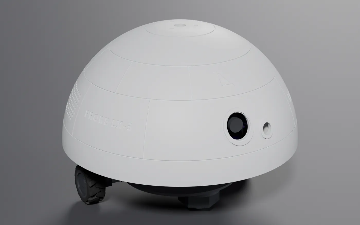
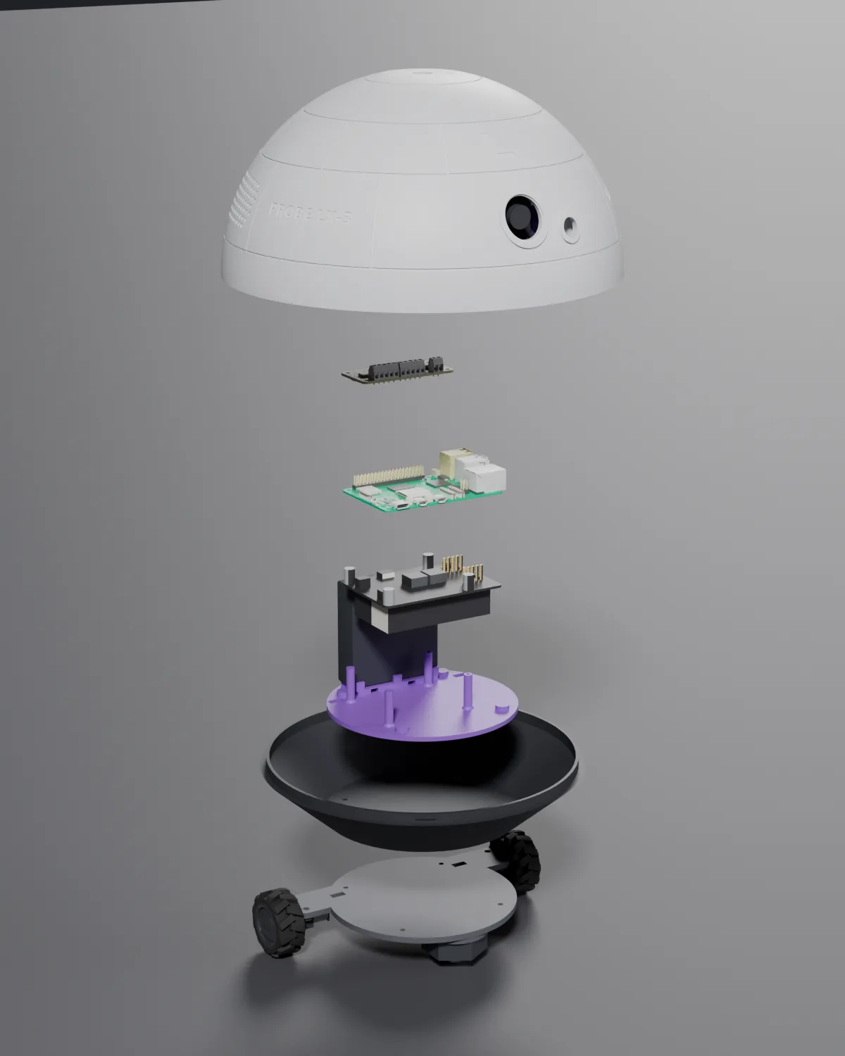
PROBE LX-3 is a small differential-drive robot: a 245 mm dome on a 209 mm base, two N20 motors at the rear and a ball caster up front. Inside is a Raspberry Pi 5 on a Geekworm X1200 UPS, an Adafruit motor bonnet, a USB camera and a VL53L1X distance sensor. The dome twist-locks onto the base, so the electronics are one quarter-turn away.
| Spec | Value |
|---|---|
| Size | Ø245 mm × about 186 mm tall, without the lidar |
| Drive | Differential, two N20 gear motors (plain or encoder) and a front ball caster |
| Compute | Raspberry Pi 5. 2 GB is enough |
| Power | Two 18650 cells on a Geekworm X1200 UPS for the Pi. Four AA cells for the motors |
| Sensors | Arducam B0385 USB camera and a CQRobot VL53L1X time-of-flight sensor |
| Motor driver | Adafruit 4280 DC + Stepper Motor Bonnet, I2C address 0x60 |
| Printed parts | Seven core parts plus one optional, all printed with no supports |
| Add-ons, no reprint | RPLIDAR A1M8 on top. WM8960 audio HAT and two speakers inside |
Directions used in this manual
Front is the camera side. Rear is the battery-cradle side. Left and right are as the robot sees them.
Hardware only
No software ships with PROBE LX-3. You get a robot with a camera, a range sensor, two drive motors and a Pi 5, and you write the software you need. The wiring section lists every bus and address.
Section 03
Parts and tools
Nothing ships with PROBE LX-3, so this is your shopping list. Brand names are the exact parts the design was modelled and fit-checked around. Swap in equivalents at your own risk, and check dimensions before you print.
Tools you will need
- 3D printer with a 256 × 256 mm bed or larger (designed on a Bambu Lab A1)
- Soldering iron with a heat-set insert tip (220–230 °C for PLA, 240–250 °C for PETG)
- Hex keys: 2.0 mm for the M3 button heads, plus 1.3 mm or 1.5 mm for M2
- Small flat screwdriver for the bonnet terminal blocks
- Tweezers or needle-nose pliers
- Masking tape
- Flush cutters
- Isopropyl alcohol for the caster pad
- Soldering gear, if your N20 motors come without leads
Optional add-ons
These are not in the box, but the shell is printed with mounts for them, so you can fit them now or come back to them later.
SLAMTEC RPLIDAR A1M8 lidar
Bolts to the dome's flat top through the optional printed adapter. Three inserts, three M3×6 screws and four M2.5 screws. No reprint.
Waveshare WM8960 Audio HAT and two 8 Ω 5 W speakers
The HAT stacks under the motor bonnet on 11 mm standoffs; the speakers zip-tie over the grilles already in the dome. No reprint.
Raspberry Pi AI HAT+ 2 (Hailo-10H, 8 GB)
Fits in the stack with an Active Cooler and runs small language models in its own memory. Uses PCIe, so nothing clashes on I2C.
| Qty | Electronics | Notes |
|---|---|---|
| 1 | Raspberry Pi 5, 2 GB or larger | 2 GB is enough. Larger boards fit the same way. |
| 1 | Geekworm X1200 2-cell 18650 UPS HAT for Pi 5 | Powers the Pi through pogo pins. Includes the spacers and M2.5×20 screws the build uses. |
| 2 | 18650 Li-ion cells | Check Geekworm's X1200 docs for the cell types it supports. |
| 1 | Adafruit 4280 DC + Stepper Motor Bonnet | Drives both N20s over I2C, address 0x60. |
| 1 | Arducam B0385 USB camera module, 38 × 38 mm board | Mounts in the dome's camera bracket, connects over USB. |
| 1 | CQRobot VL53L1X time-of-flight distance sensor, 28.5 × 23 mm board | I2C 0x29. Includes a PH2.0 cable. |
| 1 | microSD card, 32 GB or more | For the Pi's OS. |
| 1 | USB-C charger | To charge the X1200. Use the supply Geekworm recommends. |
| 4 | Female jumper wires | VL53L1X to the Pi's I2C pins, or use a 2×20 stacking header. |
| Qty | Drive and motion | Notes |
|---|---|---|
| 2 | N20 micro gear motor, standard D-shaft | Plain or encoder versions both fit. Modelled on the 12SG-N20VA-100-EN. Choose a voltage that suits a 4 × AA (about 6 V) supply. |
| 2 | N20 motor bracket with M2 screws and nuts | One per motor. |
| 1 | Ball caster, 20 mm ball, adhesive pad | Often sold as a 4-pack. You need one. |
| 1 | 4 × AA battery holder with a switch and leads | Motor power. Held on the tray cradle with zip ties. |
| 4 | AA cells | NiMH rechargeables recommended. |
| Qty | Fastener | Used for |
|---|---|---|
| 4 | M3 × 4 × 5 heat-set insert (thread × length × OD) | Electronics tray underside |
| 6 | M3 × 10 button head | 4 × plate and base to tray, 2 × camera bracket to dome |
| 4 + 4 | M2 screw and M2 nut | Motor brackets to drive plate. Use the bracket-kit screws or M2 × 8 socket pan heads. |
| 4 | M2 × 8 socket pan head | Camera to bracket, self-tapping into printed pilots |
| 2 | M2 × 5 button head | Distance sensor to bracket, self-tapping. Not M2 × 8: it bottoms out. |
| 4 | M2.5 × 20 screw | Pi 5 and X1200 to tray posts. Included with the X1200. |
| 2 | Zip tie, 4.8 mm wide, 250 mm or longer | 4 × AA pack to tray cradle |
| 2 | Short self-tapping screws (optional) | Backup for the caster pad. Max 6 mm into the pad. |
| 2 | M2.5 standoff, about 8 mm (optional) | Supports the rear edge of the motor bonnet |
| Qty | Filament | Notes |
|---|---|---|
| About 1 kg | PLA or PETG | One spool covers every rigid part. The renders use white for the dome, black for the base, grey for the drive plate and purple for the tray, bracket and lidar adapter. |
| A small amount | TPU | For the two wheel tyres. |
Section 04
Printing the parts
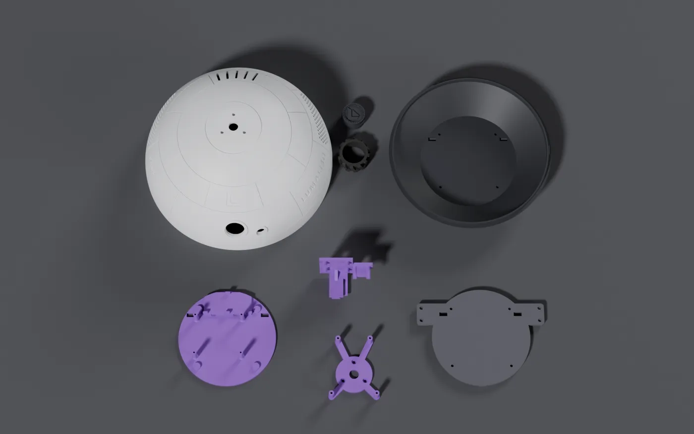
Every part is sized for a 256 mm bed, has 3 mm design walls, and prints with no supports. The dome needs at least a 245 mm circle. Everything else fits a 220 mm bed.
| Part | Size (mm) | Orientation on the bed | Notes |
|---|---|---|---|
| Dome | Ø244.8 × 120 | Rim down | Leaves 5.6 mm per side on a 256 mm bed. The inside of the top bridges about 45 mm; a little sag there is hidden. |
| Base | Ø209.4 × 41.5 | Floor down | Plain shell with 49° walls. |
| Electronics tray | Ø123 × 26 | Underside down | Carries the Pi 5 posts and the AA cradle. For electronics changes, reprint this part, not the base. |
| Drive plate | 161 × 124 × 7.5 | Top face down | Nut pockets face the bed and the caster pad faces up. |
| Camera bracket | 67 × 61 × 35.6 | Flat back face down | Holds the camera and distance sensor, and clicks into the dome's rail. |
| Wheel hub × 2 | Ø31.8 × 19 | Flat on its side, axis vertical | PLA or PETG. The D-bore presses onto the N20 shaft. |
| Wheel tyre × 2 | Ø43 × 19 | Flat on its side, axis vertical | TPU. Stretches over the hub. |
| Lidar adapter (optional) | 64 × 78 × 21.7 | Flat face down | Only for the RPLIDAR add-on. |
| Setting | Value |
|---|---|
| Material | PLA or PETG. Tyres in TPU. |
| Layer height | 0.2 mm (0.16 mm on the camera bracket for a crisper latch) |
| Wall loops | Enough to fill the 3 mm design walls, about 4 to 5 at 0.4 mm line width |
| Infill | 15 to 20 %, gyroid or grid |
| Supports | Off. No part needs them. |
| Brim | Optional on the dome and base if your bed adhesion is marginal |
After printing:
- Clear every hole: the insert holes, pilot holes, and screw holes through the plate and base.
- Push a zip tie through each speaker loop inside the dome to clear it, even if you are not fitting audio yet.
- Check the dome's ledge, the three bayonet notches and the rail block's groove for stringing.
- Test-fit the dome on the base. That is step 1.
Section 05
Shells and prep
The robot goes together bottom-up. Have everything from the parts list and all printed parts cleaned up before you start.
- 1
Test-fit the shells
- 1.Check that the dome's ledge, the three notches and the rail block's groove are clean and free of stringing.
- 2.Set the dome on the base with the camera about 30° counter-clockwise of the front, seen from above. The notches drop over the base lugs.
- 3.Twist clockwise until it stops. It should turn freely through about 30° and stop hard at each end.
Lift the dome off again. It goes back on in step 13.
- 2
Heat-set inserts in the electronics tray
You need: 4 × M3×4×5 heat-set inserts, soldering iron with an insert tip.
- 1.Turn the tray upside down on a towel.
- 2.Press an M3×4×5 insert into each of the 4 holes on the underside, straight and flush.
- 3.Let them cool for a minute before loading them.
- 3
Nuts into the drive plate
You need: 4 × M2 nuts, masking tape.
- 1.Lay the plate top face up. That is the flat face, without the pad.
- 2.Press an M2 nut into each of the 4 hex pockets on the arms. These hold the motor brackets.
- 3.Tape over all 4 pockets, then flip the plate so the raised caster pad faces up.
Section 06
Drive plate
- 1
Build the wheels and mount the motors
You need: 2 × N20 motors, 2 × printed wheel hubs, 2 × printed TPU tyres, 2 × brackets, 4 × M2 screws.
- 1.Stretch a tyre over each hub until it sits evenly all the way round.
- 2.Press a wheel onto each motor's D-shaft. Line the flat in the hub bore up with the flat on the shaft, and push the wheel fully home.
- 3.Lay a motor on each rear arm, with the wheel pointing outward and the solder tabs (or encoder board) toward the centre.
- 4.Line the gearbox's front face up with the arm tip. The wheel should sit about 1 mm clear of the tip.
- 5.Encoder motors only: the encoder board drops into the shallow pocket beside the wire slot.
- 6.Set a bracket over the gearbox with its two ears over the arm's two holes.
- 7.Drive 2 M2 screws through each bracket into the nuts. Snug them only. Overtightening crushes the gearbox.
- 8.Spin each wheel by hand. It must turn freely and not touch the plate.
- 2
Mount the caster
You need: 1 × ball caster, isopropyl alcohol.
- 1.Wipe the raised round pad clean with isopropyl alcohol if you have it.
- 2.Peel the caster's adhesive backing, centre the caster on the pad, and press hard for 30 seconds.
- 3.Optional backup: drive 2 short self-tapping screws through the caster's holes into the pad. Go no deeper than 6 mm, or they will reach the base floor.
- 3
Route the motor wires
- 1.Feed each motor's wires up through the 10 × 5 mm slot just inboard of that motor.
- 2.Remove the tape from the nut pockets.
Section 07
Chassis
- 1
Join the drive plate, base and tray
You need: 4 × M3×10 button head, 2.0 mm hex key. One set of 4 screws clamps all three parts together.
- 1.Stand the drive plate on its wheels and caster.
- 2.Set the base on the plate, lining up its 4 small holes and 2 wire slots with the plate's.
- 3.Drop the tray into the base with the posts up and the battery cradle over the motors, at the rear. Feed the motor wires up through the tray's matching slots.
- 4.Tip the assembly onto its side.
- 5.Drive 4 M3×10 button screws up through the plate and base floor into the tray inserts.
Section 08
Electronics
- 1
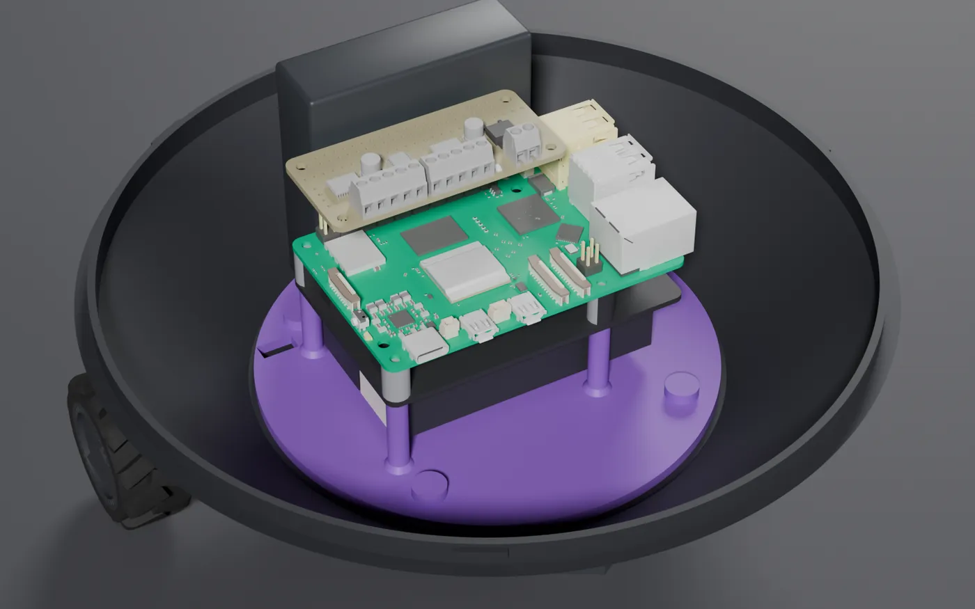
Pi 5 and X1200 stack
You need: Pi 5, X1200 with its spacers and 4 × M2.5×20 screws, 2 × 18650 cells.
- 1.Fit both 18650 cells into the X1200 first. The holders face down, and you cannot reach them once the stack is in.
- 2.Set the Pi 5 on the X1200 with the spacers between them, so the pogo pins meet the pads on the Pi's underside.
- 3.Stand the stack on the 4 tray posts, with the 40-pin header toward the rear and the USB and Ethernet end toward the robot's left.
- 4.Drive 4 M2.5×20 screws down through the Pi 5, spacers and X1200. The tips cut their own thread into the posts. Stop at snug.
- 2
Motor bonnet
- 1.Press the motor bonnet straight down onto the Pi's 40-pin header.
Optional: fit two 8 mm M2.5 standoffs in the Pi's rear holes to support the bonnet.
- 3
4AA battery pack
You need: 4 × AA holder, 2 × zip ties, 250 mm or longer.
- 1.Stand the pack on its edge on the rear cradle, between the ribs.
- 2.Thread 2 zip ties through the tunnels under the cradle, up both faces of the pack, and over the top.
- 3.Put the tie heads on top of the pack, pull tight, and trim.
- 4
Base wiring
You need: small flat screwdriver.
- 1.Left motor to bonnet terminal M1. Right motor to M2. If a wheel runs backward in testing, swap that motor's two wires.
- 2.4AA pack leads to the bonnet's motor power terminal, red to +. Leave the pack switched off, or leave a cell out.
Section 09
Dome
- 1
Camera and distance sensor into the dome
You need: camera bracket, Arducam B0385, VL53L1X, 4 × M2×8 socket pan, 2 × M2×5 button, 2 × M3×10 button. Load the bracket on the bench first, then slide it into the dome.
- 1.Camera: with the lens facing away from the bracket, set the board on the 4 short standoffs. Gently drive 4 M2×8 socket pan screws through the board into the standoffs. Plug the camera cable in through the window in the bracket plate.
- 2.Distance sensor: plug its cable in first, with the connector facing down. Set the board on the 2 long standoffs with the chip facing away from the bracket, and fix it with 2 M2×5 button screws.
- 3.Set the dome upside down on a towel. Find the rail block on the ledge below the camera opening.
- 4.Hold the bracket with the lens toward the opening. Drop the dovetail key into the open end of the groove and push the bracket toward the wall.
- 5.The latch rides up over the block and clicks into its notch as the key hits the end stop. The lens now sits in the Ø24 opening, and the sensor chip faces its window.
- 6.On the dome's rim face below the camera, find the two recessed holes. Drive 2 M3×10 button screws up through them into the bracket key until snug. The heads sit below the rim face, so the dome still seats on the base.
- 7.Route both cables down toward the base with at least 70 mm of slack. They must reach the Pi with the dome unlocked.
To remove the bracket
Take out the 2 screws, push the latch arm up (toward the dome top) where it passes the end of the block, and slide the bracket back out.
- 2
Connect and close
- 1.Camera USB lead to any Pi USB port.
- 2.Distance sensor to the Pi's I2C pins: 3.3 V, GND, SDA (GPIO2), SCL (GPIO3). Reach them through the bonnet's pass-through pads or a stacking header. The sensor (0x29) and the bonnet (0x60) use different addresses.
- 3.Tuck the cables so nothing crosses the base lugs.
- 4.Set the dome on about 30° counter-clockwise, then twist clockwise to the stop. The camera now faces the front, over the caster.
To open: twist counter-clockwise to the stop and lift.
Section 10
Wiring reference
Every connection in one table, and the I2C addresses to expect. Leave at least 70 mm of slack on every cable that runs from the dome to the base: the dome twists 30° to unlock, and nothing should pull on a plug.
| From | To | Notes |
|---|---|---|
| X1200 | Pi 5 | Pogo pins to the pads on the Pi's underside. No wires. |
| Motor bonnet | Pi 5 | Pressed onto the 40-pin header |
| Left N20 motor | Bonnet M1 | If the wheel runs backward, swap the two wires |
| Right N20 motor | Bonnet M2 | Same as the left motor |
| 4 × AA pack | Bonnet motor power terminal | Red to +. This powers the motors only, not the Pi. |
| Arducam B0385 | Any Pi USB port | |
| VL53L1X VIN | Pi 3.3 V (pin 1) | Through the bonnet's pass-through pads or a stacking header |
| VL53L1X GND | Pi GND (pin 6) | |
| VL53L1X SDA | Pi GPIO2 / SDA (pin 3) | |
| VL53L1X SCL | Pi GPIO3 / SCL (pin 5) |
| Address | Device | Present |
|---|---|---|
| 0x1a | WM8960 audio codec | Audio add-on only |
| 0x29 | VL53L1X distance sensor | Always |
| 0x60 | Motor bonnet (PCA9685 PWM) | Always |
| 0x70 | Motor bonnet all-call address | Always |
i2cdetect -y 1Check the bus
Section 11
Checks before first power-on
Run these with the robot on the bench before its first drive.
- Both wheels and the caster touch the table, and the robot sits level.
- The wheels spin freely by hand, about 1 mm clear of the plate arms.
- The robot does not tip backward when rocked. The caster stays loaded.
- The dome twists through its full 30° both ways with all cables connected and no pull on the plugs.
- The 4AA leads are on the bonnet's motor power terminal with correct polarity before the last cell goes in.
- The 18650 cells are charged, and the Pi boots from the X1200 alone.
- lsusb shows the camera, and i2cdetect -y 1 shows 0x29 (distance sensor) and 0x60 (bonnet).
- Each wheel turns forward on a forward command. If one does not, swap that motor's two wires at the bonnet.
- Audio add-on only: i2cdetect -y 1 also shows 0x1a (WM8960), and both speakers play.
Section 12
Writing your own software
PROBE LX-3 ships with no software. Use whatever language or framework you like. Here is what each device needs from the Pi.
| Device | Interface | Where to start |
|---|---|---|
| Drive motors, via the Adafruit 4280 bonnet | I2C 0x60 | Adafruit's DC & Stepper Motor Bonnet guide and the adafruit-circuitpython-motorkit library. M1 is the left motor and M2 is the right. |
| Camera, Arducam B0385 | USB (UVC) | Appears as /dev/video*. Use OpenCV, GStreamer, ffmpeg, or any V4L2 tool. |
| Distance sensor, VL53L1X | I2C 0x29 | Any VL53L1X driver. It points forward, next to the camera. |
| UPS and battery, X1200 | See Geekworm's docs | Geekworm's X1200 wiki covers battery-level and power-loss monitoring. |
| Lidar, RPLIDAR A1M8 (optional) | USB serial | SLAMTEC's SDK, or the rplidar_ros package for ROS 2. The lidar motor faces the rear. |
| Audio, WM8960 HAT (optional) | I2S and I2C 0x1a | Waveshare's WM8960 HAT driver. It includes microphones for voice. |
Some ideas: teleop over Wi-Fi, obstacle avoidance with the ToF sensor, follow-me with camera vision, SLAM mapping with the lidar, or a voice assistant with the audio HAT and an AI HAT+ 2.
Fitting the lidar?
It adds about 170 g at the top of the dome. Keep acceleration and braking gentle in your software.
Files and updates
The STLs, the Blender source model, the PDF version of this manual and the add-on guides are in the repository at github.com/patmakesapps/PROBE-LX-3, under CC BY-SA 4.0. Built one, or wrote software for it? Open an issue there and we will list it.
Something not matching up?
If a part is missing, damaged, or your kit does not match a step, stop and get in touch before continuing.